Subaru EJ25 Spark Plug Wire Diagram: Cylinders, Coil Pairs and COP Warning
Subaru EJ25 plug-wire routing guide covering cylinder positions, firing order 1-3-2-4, waste-spark pairs, coil tower verification.
On a longitudinal Subaru EJ25, cylinders 1 and 3 are on the right/passenger bank from front to rear, while cylinders 2 and 4 are on the left/driver bank from front to rear. Subaru specifies the firing order as 1-3-2-4. On EJ25 versions with one central four-tower waste-spark coil and high-tension wires, the functional companion pairs are 1 with 2 and 3 with 4. However, the molded physical tower locations are application-specific—follow the numbers on the coil and the exact Subaru service diagram. Later EJ25 variants may use individual coil-on-plug units and have no plug-wire routing.
Subaru's horizontally opposed engine places two cylinders on each side of the vehicle instead of in one row. That makes a generic inline-four sketch worse than useless: it can send a correct sequence to the wrong physical bank. Start every EJ25 routing job by marking the vehicle front and viewing the engine in its installed orientation.
Subaru's own EJ25 technical specification gives the 1-3-2-4 firing order, while its 2004 warranty literature separately identifies ignition wires, ignition coil and ignitor as system components on applicable vehicles. Those sources establish the engine facts and the existence of a high-tension-wire architecture, but the EJ25 family later includes COP arrangements. A VIN/year/engine-code check remains mandatory.
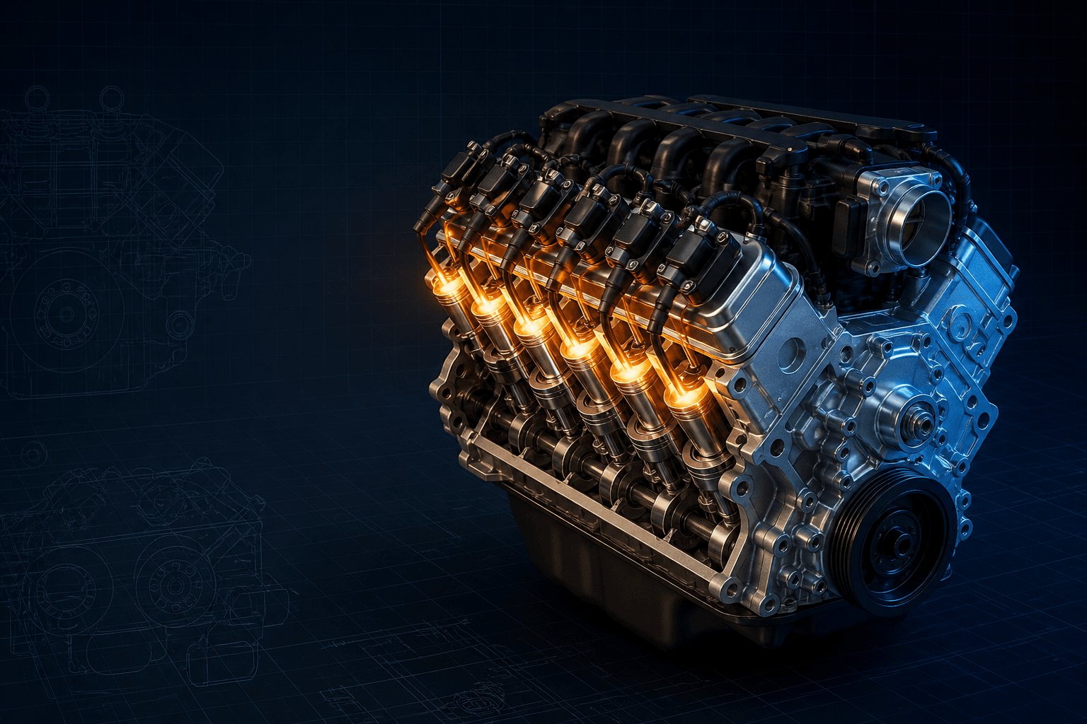
Interactive EJ25 cylinder and plug-wire map
Branded downloads includedPNG and PDF exports carry the TorqueSheet logo, torquesheet.com, source-page URL, and republishing attribution request. The PDF source link is clickable.
The map shows cylinder positions and companion pairs. Read molded coil-tower numbers or the exact Subaru manual before attaching the four leads.
Subaru Ej25 Spark Plug Wire Diagram
| APPLICATION / ITEM | SPECIFICATION | NOTES |
|---|---|---|
| Right/passenger bank | 1 front, 3 rear | Viewed in the installed vehicle |
| Left/driver bank | 2 front, 4 rear | Viewed in the installed vehicle |
| Firing order | 1-3-2-4 | Confirmed by Subaru technical information |
| Waste-spark companions | 1/2 and 3/4 | For shared-coil high-tension-wire systems |
| Later-system warning | Coil-on-plug may have no wires | Identify engine/year before ordering |
A flat-four diagram is easy to mirror accidentally. Establish vehicle front, right/passenger bank and left/driver bank before assigning cylinders. Never route by shortest wire alone, and never force a four-wire diagram onto a COP engine.
How to use this specification correctly
- 01
Record VIN, model year, Legacy/Outback/Forester/Impreza/Baja application, turbo/non-turbo status and full engine identification.
- 02
Confirm whether the engine has one four-tower coil plus four high-tension leads or individual coils mounted at the plugs.
- 03
Mark vehicle front, then label right-bank cylinders 1 and 3 and left-bank cylinders 2 and 4 before removing leads.
- 04
Photograph the original coil and read every molded tower number. If numbers are missing, retrieve the exact Subaru ignition-system illustration.
- 05
Replace one wire at a time, seating each boot fully and preserving factory separators, heat shields and crossing geometry.
- 06
Measure wire resistance only against the application-specific limit; compare lead length and terminal condition rather than using one universal ohms figure.
- 07
Start the engine in darkness only with normal safety precautions to look for arcing, then verify misfire counters under load with a scan tool.
EJ25 cylinder positions
With the engine installed longitudinally, cylinder 1 is the right-front cylinder and 3 is right-rear. Cylinder 2 is left-front and 4 is left-rear. Here right and left are vehicle directions, not the technician's perspective while standing in front of the bumper.
A drawing copied from a right-hand-drive forum may still use vehicle right/left correctly, but labels such as passenger side become market-dependent. Use bank numbers and vehicle directions first.
Waste-spark coil pairing
On the shared four-tower arrangement, each internal secondary coil fires a companion pair. With the 1-3-2-4 sequence, cylinders 1 and 2 form one companion pair and 3 and 4 form the other; one cylinder is on compression while its companion is on exhaust.
This pairing explains circuit operation but does not prove which corner of a particular coil is tower 1, 2, 3 or 4. Molded markings and the application diagram are authoritative because replacement coils and mounting orientation can differ.
Coil-on-plug boundary
Some later and turbo EJ25 applications place an individual coil at each spark plug. These engines retain the basic cylinder numbering and firing order but eliminate the four long secondary wires and central tower-routing problem.
If a parts listing offers both wire sets and COP coils for a broad year range, refine the lookup by VIN, emissions specification and engine code. A vehicle may also have a swapped engine or intake/ignition arrangement.
Wire routing and installation
- Work on a cool engine; exhaust headers are close to the plug wells.
- Pull on the boot, not the cable, and twist gently to break the seal.
- Use dielectric grease only as directed at the boot seal; do not coat electrical contact surfaces indiscriminately.
- Keep leads in the original separators to prevent abrasion and inductive crossfire.
- Avoid tight bends and contact with the timing covers, accessory belts and exhaust shields.
- Listen and feel for the terminal engaging the plug and tower; a loose boot can arc internally.
Misfire diagnosis
A cylinder-specific misfire can come from a damaged lead, cracked coil, carbon-tracked boot, wrong plug, injector fault, vacuum leak, compression loss or valve/timing problem. Inspect both ends of the lead and the plug-well area before condemning the coil.
Because a waste-spark coil serves two cylinders, simultaneous faults in a companion pair can point toward a shared secondary or primary circuit. One isolated cylinder more often directs attention to its lead, plug, injector or mechanical condition, but testing must confirm the cause.
Editorial verification status
TorqueSheet has verified the EJ25 firing order from Subaru and separated high-tension-wire from COP architectures. This page remains indexable but visibly limited until factory tower-layout figures are attached for defined model-year/application groups rather than presented as one universal EJ25 coil drawing.
Subaru EJ25 Flat-Four specifications can change by model year, engine, platform, wheel, and installed component. Confirm the VIN or engine identity, part numbers, fastener condition, and the current manufacturer instructions before service.
Subaru EJ25 Spark Plug Wire Diagram: Cylinders, Coil Pairs and COP Warning FAQs
What is the Subaru EJ25 firing order?+
Subaru specifies 1-3-2-4.
Where is cylinder 1 on an EJ25?+
Cylinder 1 is at the front of the right/passenger-side bank in a typical left-hand-drive longitudinal installation.
Which cylinders share a coil on a waste-spark EJ25?+
The functional companion pairs are 1/2 and 3/4. Use coil markings for the exact physical tower locations.
Does every EJ25 use spark plug wires?+
No. Some EJ25 variants use individual coil-on-plug units and do not have a four-wire set.
Can I route the wires by length?+
No. Length can help confirm a factory route, but cylinder and molded tower numbers must control the connection.
Technical sources
TorqueSheet favors engine- and component-specific manufacturer instructions over unsourced universal values.
1Subaru STI EJ25 engine specificationSubaru's technical-information manual identifies the EJ25 as a horizontally opposed four-cylinder and specifies the firing order as 1-3-2-4.↗22004 Subaru Warranty and Maintenance BookletSubaru's booklet lists resistor spark plugs, ignition wires, ignition coil, ignitor, relay and related wiring as distinct emissions-system components on applicable vehicles.↗3Subaru Owner's Information PortalSubaru's VIN/model selector is the official path to application-specific owner resources; service-level tower and harness routing still requires the matching Subaru service information.↗