Nissan SR20DET Coil Pack Wiring: S13/S14 Igniter vs. S15 Smart Coils
Nissan SR20DET coil wiring guide covering cylinders 1-4, firing order 1-3-4-2, S13/S14 external power transistor, S15 integrated-igniter coils, power.
The Nissan SR20DET is a four-cylinder coil-on-plug engine with cylinder 1 at the front/crank-pulley end and cylinder 4 at the rear/transmission end; its firing order is 1-3-4-2. S13 and S14 Silvia/180SX/200SX systems commonly route four ECU ignition commands through an external power-transistor/igniter unit before the four coils. S15 SR20DET coils integrate the ignition power stage, so their connector functions and ECU interface are not wired like S13/S14 coils. Do not bypass or retain an igniter until the exact coil type and ECU output strategy are confirmed.
SR20DET swaps often arrive as a box of parts described only as redtop, blacktop or S15. Those color labels are insufficient for wiring. A harness may have been repinned, the original external igniter may be missing, or the engine may use aftermarket smart coils. Before applying power, identify the ECU, coil part numbers, cam-angle sensor, engine harness and donor chassis separately.
Nissan's S14 factory workshop manual provides the clearest architecture reference for that generation: the ECM sends ignition signals to a power transistor, which switches the primary circuits of compact coils mounted directly over the plugs. S15 conversions remove that external stage only when coils with the correct integrated igniters and signal requirements are installed.
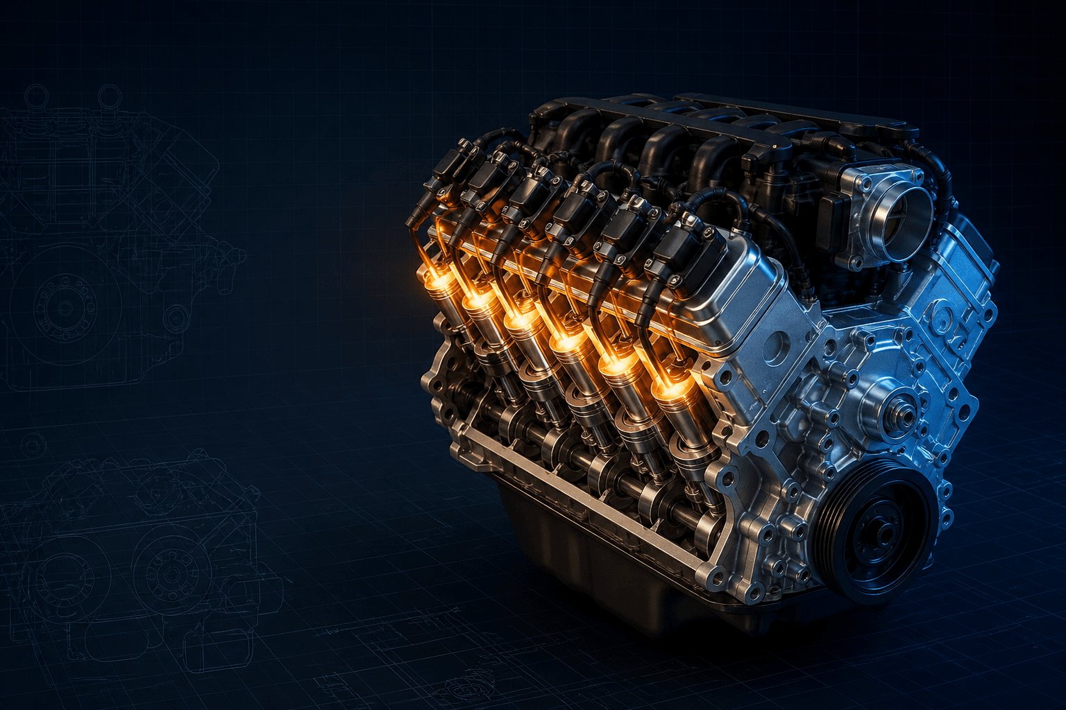
Interactive SR20DET ignition architecture map
Branded downloads includedPNG and PDF exports carry the TorqueSheet logo, torquesheet.com, source-page URL, and republishing attribution request. The PDF source link is clickable.
Choose S13/S14 or S15 architecture first. The exact connector cavities and ECU terminals must come from the donor's Nissan manual.
Nissan Sr20det Coil Pack Wiring Diagram
| APPLICATION / ITEM | SPECIFICATION | NOTES |
|---|---|---|
| Cylinder order | 1-2-3-4 | Front pulley end toward transmission |
| Firing order | 1-3-4-2 | Separate from physical harness order |
| S13/S14 strategy | ECU -> external igniter -> coils | Confirmed for the referenced S14 factory manual |
| S15 strategy | Integrated-igniter coils | Different primary interface; identify genuine coil/harness |
| Swap requirement | Match ECU + CAS + igniter/coil + harness | Do continuity mapping before power-up |
The S14 factory manual explicitly describes the ECM signal being amplified by a power transistor that switches each coil primary. That architecture-level fact is reliable for the referenced S14, but ECU pins, colors, igniter connector cavities and relay paths differ across S13, S14, S15, 180SX, 200SX and swapped chassis.
How to use this specification correctly
- 01
Record donor chassis/market, production year, engine number, ECU part number, harness identity, coil part numbers and whether an external igniter is present.
- 02
Mark the crank-pulley/front end and label cylinders and coils 1 through 4 toward the transmission.
- 03
Retrieve the Nissan engine-control and electrical sections for the exact S13, S14 or S15 donor; do not use a US 240SX KA diagram as an SR20DET pinout.
- 04
With power disconnected, continuity-map ECU commands through the external igniter on S13/S14 or directly to appropriate smart-coil inputs on S15/conversions.
- 05
Verify ignition relay output, coil power and head/harness grounds under load before condemning the ECU or cam-angle sensor.
- 06
Use a scope with correct grounding and attenuation to inspect CAS references and ignition commands; never connect an ECU logic output directly to a high-current dumb coil.
- 07
After repair, verify 1-3-4-2 operation, timing synchronization and cylinder-specific misfire behavior under controlled load.
Cylinder numbering and sequence
Cylinder 1 is at the front accessory/crank-pulley end, followed by 2, 3 and 4 toward the gearbox. The firing order is 1-3-4-2. The physical row of connectors will normally appear 1-2-3-4, but the ECU schedules events in the firing sequence.
On an engine stand, define front by the crank pulley rather than by which direction the engine happens to face. Misidentifying the ends can reverse all four injector and ignition assignments while the connectors still appear neatly routed.
S13/S14 external power transistor
The referenced S14 Nissan manual states that the ECM ignition signal is amplified by the power transistor, which turns the coil primary on and off to induce secondary voltage. In functional terms, the ECU provides timed commands, the external igniter supplies the high-current switching stage and each coil delivers spark to its plug.
A missing external module cannot be replaced by joining the ECU wires straight to factory dumb coils. Doing so risks no spark and ECU damage. Test power, ground, command-in and coil-control-out according to the exact connector views.
S15 and smart-coil conversions
S15-style coils incorporate the ignition power stage, so they need appropriate power, ground and logic-level trigger functions at each coil. Their connectors and electrical loading differ from earlier coils that rely on the separate igniter.
Aftermarket R35, VAG or other smart-coil conversions add dwell and grounding requirements. A plug-in sub-harness is not proof that the ECU calibration has the correct dwell, edge polarity or output protection; follow the coil-kit and ECU manufacturer's primary documentation together.
Power and grounding checks
- Identify the ECCS/ignition relay and fuse from the donor schematic.
- Measure coil supply voltage during cranking, not only key-on with no load.
- Voltage-drop test engine-to-battery and harness grounds while cranking.
- Confirm the igniter heat sink/mount and connector locks on external-module systems.
- Separate sensor grounds from high-current coil grounds in conversions.
- Do not ground a scope through a path that can carry starter or coil current.
No-start and misfire logic
No command on all four channels directs diagnosis upstream to power, ECU enable, immobilizer where applicable, CAS signals and common grounds. One dead channel points more strongly toward its ECU-to-igniter wire, igniter channel, coil connector or coil, although compression and fuel must still be tested.
A timing light or scope can confirm that spark exists without proving it occurs on the correct cylinder. After repinning, verify command-to-cylinder continuity and base timing using the Nissan procedure rather than rotating the CAS until the engine merely runs.
Editorial verification status
TorqueSheet has anchored the S14 architecture to Nissan's factory manual and separates the S15 smart-coil design. This broad SR20DET page remains indexable but visibly limited until complete factory connector figures are attached for S13, S14 and S15 donor variants with market-specific ECU pin tables.
Nissan SR20DET Inline-Four specifications can change by model year, engine, platform, wheel, and installed component. Confirm the VIN or engine identity, part numbers, fastener condition, and the current manufacturer instructions before service.
Nissan SR20DET Coil Pack Wiring: S13/S14 Igniter vs. S15 Smart Coils FAQs
What is the SR20DET firing order?+
The inline-four firing order is 1-3-4-2.
Where is cylinder 1 on an SR20DET?+
Cylinder 1 is at the front/crank-pulley end; cylinder 4 is nearest the transmission.
Does an S14 SR20DET need an igniter chip?+
The referenced factory S14 system uses an external power-transistor unit between the ECM commands and coils.
Can S15 coils be wired through the S14 igniter?+
Do not assume so. S15-style coils integrate their power stage and require a correctly designed bypass/repin strategy plus suitable ECU dwell.
Why is there power at all coils but no spark?+
Check ECU enable, CAS reference/position signals, grounds, ignition commands and the external igniter where fitted; power alone is only one part of the circuit.
Technical sources
TorqueSheet favors engine- and component-specific manufacturer instructions over unsourced universal values.
1Nissan S14/200SX factory workshop manual - engine controlThe Nissan workshop-manual scan describes an external power transistor amplifying ECM ignition commands and four molded coils mounted directly on the spark plugs for the S14 SR20DET.↗2Nissan Silvia S15 Spec-R factory specificationNissan's historical vehicle specification identifies the S15 Spec-R's SR20DET application, anchoring the later variant to a specific chassis rather than a generic SR engine.↗3Nissan historical SR20DET engine pageNissan's own historical archive identifies the SR20DET engine family; connector-level service data still depends on the chassis and production version.↗