Ford 6.0 Power Stroke Head Bolt Torque Specs and Sequence
Ford 6.0 Power Stroke Head Bolt Torque Specs and Sequence with application boundaries, fastener distinctions.
For the covered 2004 F-350 6.0L Power Stroke, use new head bolts: tighten main bolts 1–10 to 65 lb-ft; take odd-numbered main bolts 1, 3, 5, 7 and 9 to 85 lb-ft; then turn all main bolts 90° three times. Tighten small bolts 11–15 to 18 and then 23 lb-ft.
For the covered 2004 F-350 6.0L Power Stroke, use new head bolts: tighten main bolts 1–10 to 65 lb-ft; take odd-numbered main bolts 1, 3, 5, 7 and 9 to 85 lb-ft; then turn all main bolts 90° three times. Tighten small bolts 11–15 to 18 and then 23 lb-ft.
The exact stages apply to the documented 2004 Super Duty 6.0L factory-bolt procedure. Later service revisions, E-Series packaging, machined assemblies, nonstandard gaskets and stud conversions must use their matching instructions.
The 85-lb-ft stage does not apply to every main bolt, and the five small bolts do not receive the 90° turns. Keep both fastener groups labeled and record every completed angle pass; aftermarket studs replace this factory torque-to-yield procedure completely.
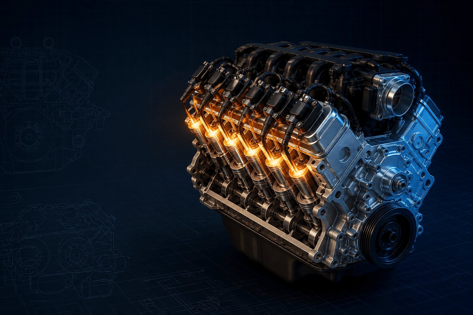
Interactive 2004 F-350 6.0L Power Stroke V8 head sequence aid
Branded downloads includedPNG and PDF exports carry the TorqueSheet logo, torquesheet.com, source-page URL, and republishing attribution request. The PDF source link is clickable.
Orientation aid only. Use the exact manufacturer bolt map and stages for assembly.
Ford 6.0 Powerstroke Head Bolt Torque Specs
| APPLICATION / ITEM | SPECIFICATION | NOTES |
|---|---|---|
| Main bolts 1–10 — stage 1 | 65 lb-ft | 88 N·m; new bolts |
| Odd main bolts 1,3,5,7,9 | 85 lb-ft | 115 N·m; position-specific stage |
| All main bolts 1–10 | 90° + 90° + 90° | Three clockwise sequence passes |
| Small bolts 11–15 | 18 then 23 lb-ft | 24 then 31 N·m; no angle turn |
| Stud conversion | Stud-maker chart | Do not mix procedures |
The 85-lb-ft stage does not apply to every main bolt, and the five small bolts do not receive the 90° turns. Keep both fastener groups labeled and record every completed angle pass; aftermarket studs replace this factory torque-to-yield procedure completely.
How to use this specification correctly
- 01
Identify the engine serial/RPO, model year, cylinder head, gasket and fastener kit.
- 02
Verify flatness, surface finish, threads and empty bolt holes.
- 03
Complete each torque, loosen and angle stage in the exact numbered order.
Separate the ten main bolts from five small bolts
Ford requires new head bolts in the covered 2004 procedure. Main bolts 1–10 first receive 65 lb-ft, but only odd positions 1, 3, 5, 7 and 9 receive the intermediate 85-lb-ft step. All ten main bolts then receive three separate 90° turns in sequence.
Small bolts 11–15 are a separate group. They tighten to 18 lb-ft and then 23 lb-ft and do not receive any of the three angle turns.
Recording three full angle passes
Use a stable angle gauge and mark each main bolt after every completed pass. Finish all ten positions through one 90° sequence before starting the second, and complete the second before the third; one estimated 270° movement is not the published workflow.
If the wrench movement becomes abnormal or a bolt does not seat normally, stop. Do not reverse a finished angle to correct a paint mark without following the service procedure for a restarted installation.
Why stud-conversion instructions replace this chart
The factory procedure is built around new torque-to-yield bolts. A stud kit changes the fastener, thread friction, washer system and clamp calculation, so it uses the kit maker's lubricant and torque stages instead of Ford's 90° passes.
Cylinder-head and block flatness, surface finish and gasket choice also remain critical. More clamp load cannot compensate for an improperly prepared sealing surface.
Application boundaries for 2004 F-350 6.0L Power Stroke V8
The exact stages apply to the documented 2004 Super Duty 6.0L factory-bolt procedure. Later service revisions, E-Series packaging, machined assemblies, nonstandard gaskets and stud conversions must use their matching instructions.
The 85-lb-ft stage does not apply to every main bolt, and the five small bolts do not receive the 90° turns. Keep both fastener groups labeled and record every completed angle pass; aftermarket studs replace this factory torque-to-yield procedure completely.
Ford 2004 F-350 6.0L Power Stroke V8 specifications can change by model year, engine, platform, wheel, and installed component. Confirm the VIN or engine identity, part numbers, fastener condition, and the current manufacturer instructions before service.
Ford 6.0 Power Stroke Head Bolt Torque Specs and Sequence FAQs
What are the 2004 Ford 6.0 Power Stroke main head-bolt stages?+
Tighten bolts 1–10 to 65 lb-ft, bolts 1/3/5/7/9 to 85 lb-ft, then turn all ten main bolts 90° three separate times.
What torque applies to 6.0L small head bolts 11–15?+
The covered procedure uses 18 lb-ft followed by 23 lb-ft, with no angle turn for that small-bolt group.
Can the covered 6.0 Power Stroke head bolts be reused?+
No. Ford's cited specification explicitly requires new cylinder-head bolts.
Do 6.0 Power Stroke studs use the factory angle stages?+
No. Use the stud maker's torque, lubricant and sequence instead of mixing the two systems.
Technical sources
TorqueSheet favors engine- and component-specific manufacturer instructions over unsourced universal values.
1Ford owner manualsOfficial Ford year/VIN manual lookup.↗