Chevy 5.3 Knock Sensor Harness Diagram: Gen III vs. Later Engines
Chevy 5.3 knock-sensor harness guide separating Gen III LM7/L59/LM4 valley sensors from later side-of-block layouts, with front/rear circuits.
On common Gen III 5.3L LM7/L59/LM4 engines, two one-wire knock sensors thread vertically into wells beneath the intake manifold. The short sub-harness connects the front and rear sensors to an external engine-harness connector near the rear/top of the intake area; each sensor grounds through its threaded contact with the block. GM identifies P0327 with the front sensor circuit and P0332 with the rear sensor circuit. Later 5.3L generations can use sensors on the sides of the block with different two-wire-style circuits and no interchangeable valley sub-harness.
The familiar 5.3 knock-sensor job—remove the intake and find two round sensors in the valley—applies to a major Gen III truck-engine group, not every 5.3 ever installed in a Chevrolet. Later engines moved sensors outside the valley and changed electrical design. Search by RPO such as LM7, L59, LM4, LY5, LC9, LMG, L83 or L84 rather than by displacement alone.
On the valley system, the sub-harness is part of the measurement circuit. Each sensor generates a small vibration signal referenced through its block contact. Corrosion in a sensor well, a loose terminal, high-resistance splice, shield/routing damage or incorrect sensor torque can distort the signal even when the new sensor's connector clicks.
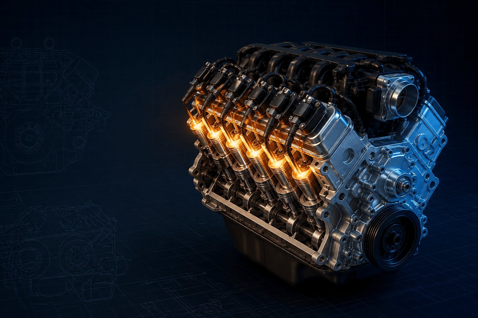
Interactive 5.3L knock-sensor harness map
Branded downloads includedPNG and PDF exports carry the TorqueSheet logo, torquesheet.com, source-page URL, and republishing attribution request. The PDF source link is clickable.
Choose the engine generation first. The Gen III branch shows front/rear valley circuits; later engines require the RPO-specific side-sensor diagram.
Chevy 5.3 Knock Sensor Harness Diagram
| APPLICATION / ITEM | SPECIFICATION | NOTES |
|---|---|---|
| Gen III sensor 1 | Front valley sensor | GM associates its low-circuit monitor with P0327 |
| Gen III sensor 2 | Rear valley sensor | GM associates its low-circuit monitor with P0332 |
| Sub-harness path | Two sensors → rear/top external connector | Retained under/along intake according to application |
| Gen III grounding | Sensor shell/thread to block | Clean dry seat and exact torque are signal-critical |
| Later-generation warning | External side-of-block sensors | Different harness/sensor strategy; identify RPO |
‘Chevy 5.3’ spans Gen III, Gen IV and Gen V engine codes. Confirm RPO and year before buying sensors or a harness. A harness that plugs in physically may still have the wrong connector keying, terminal assignment, sensor calibration or length.
How to use this specification correctly
- 01
Confirm VIN year and engine RPO, then visually determine whether sensors are under the intake or mounted externally on the block.
- 02
Scan all codes and record freeze-frame data. On the Gen III two-valley-sensor strategy, separate P0327/front from P0332/rear rather than replacing parts solely by the word ‘bank.’
- 03
Disconnect battery power as directed, relieve fuel-system pressure and follow the exact intake-manifold removal procedure; prevent debris from entering ports.
- 04
Inspect the external connector, sub-harness insulation, terminal tension, seals, sensor wells, valley cover and evidence of water/coolant/oil entry before removal.
- 05
Clean and dry the threaded seats without changing geometry. Install correct sensors and harness with the specified torque and connector retention; do not use thread tape that isolates the ground path.
- 06
Apply only the water-diversion method specified for the exact GM bulletin/application. Do not encircle a well in a way that traps water or seal every valley drain.
- 07
Reassemble with correct intake seals and torque sequence, then clear codes and run the GM enable/verification conditions instead of assuming an immediate idle check proves the repair.
Gen III valley harness layout
The short harness has one branch to the forward sensor and another to the rear sensor. It exits the covered valley to meet the main engine harness at an external connector near the rear/top intake area. The sensor bodies complete their electrical reference through clean threaded contact with the block.
GM's diagnostic parameters label sensor 1 as front and sensor 2 as rear. This is clearer than borrowing oxygen-sensor ‘bank’ terminology, because both sensors monitor structure-borne vibration and are physically centered in the valley rather than screwed into individual cylinder banks.
Water intrusion and the rear sensor
GM Corporate Bulletin 02-06-04-023 addressed specified early vehicles with P0332 and rear-sensor corrosion caused by water entering the valley well. Its repair creates a diversion dam with an intentional opening; it is not an instruction to bury sensors/connectors in sealant.
Later years, replacement intake seals and prior repairs must be evaluated separately. Find the water path—washing, cowl leakage, coolant spill, failed seals or trapped debris—and keep designed drainage available.
Why sensor torque and seat condition matter
A piezoelectric knock sensor is mechanically coupled to the block. Incorrect torque, rust scale, sealant, a damaged thread or a relocated mounting point changes that coupling and therefore the frequency/amplitude seen by the controller.
Do not relocate a failed valley sensor to a convenient head or bellhousing bolt as a universal fix. Even if a code disappears, the calibrated knock-detection response is no longer assured.
Gen IV and Gen V boundary
Many later LS-based and EcoTec3 5.3L engines use externally mounted sensors on the sides of the block and different wiring. Sensor count may remain two, but connector, pin count, bias strategy, mounting torque and ECM terminals are not the Gen III valley system.
Identify the RPO and retrieve the exact schematic before continuity or resistance testing. Applying a one-wire valley-sensor test to a later two-wire circuit can produce false conclusions or damage a terminal.
Circuit diagnosis before intake removal
- Confirm code definition and enable conditions for the exact ECM calibration.
- Inspect the accessible external connector for oil, water, loose lock or terminal spread.
- Check main-harness routing near brackets, grounds and prior repairs.
- Use only GM-specified resistance, bias-voltage, signal or induced-knock tests; generic values vary by sensor design.
- Do not strike the engine or sensor hard enough to damage components while trying to create a signal.
Chevrolet 5.3L V8 specifications can change by model year, engine, platform, wheel, and installed component. Confirm the VIN or engine identity, part numbers, fastener condition, and the current manufacturer instructions before service.
Chevy 5.3 Knock Sensor Harness Diagram: Gen III vs. Later Engines FAQs
Which 5.3 knock sensor is sensor 1?+
On the common Gen III LM7-style valley system, GM identifies sensor 1 as the front sensor and sensor 2 as the rear sensor.
What codes correspond to the Gen III 5.3 knock sensors?+
GM's two-sensor diagnostic material associates P0327 with the front/sensor-1 low circuit and P0332 with the rear/sensor-2 low circuit. Confirm the exact calibration.
Do the valley knock sensors need a ground wire?+
The common one-wire Gen III sensors use their threaded mechanical contact with the block as the electrical reference. Clean seating and exact torque matter.
Should I seal completely around both knock sensors?+
No universal instruction says to trap them in sealant. The early GM water-intrusion bulletin used a specific diversion dam and left an opening. Follow the exact application procedure.
Why does my 5.3 have knock sensors on the side of the block?+
It is likely a later engine generation or different RPO. It does not use the same valley harness diagram.
Technical sources
TorqueSheet favors engine- and component-specific manufacturer instructions over unsourced universal values.
1GM 2001 engine diagnostic parameters — LM7 knock circuitsGM identifies P0327 as the front knock-sensor circuit and P0332 as the rear knock-sensor circuit on the two-sensor 5.3L LM7 application.↗2GM 2004 engine diagnostic parameters — 5.3L applicationsGM lists the LM7, L59 and LM4 5.3L knock-sensor circuit monitoring strategy and applicable diagnostic codes.↗3GM Corporate Bulletin 02-06-04-023 archived copyThe GM bulletin documents rear valley-sensor corrosion from water intrusion on specified 1999–2002 LR4/LM7/L59/LQ4/LQ9 vehicles and gives an application-limited repair procedure.↗